
Setting the coverslip position.
The coverslip position (or distance) parameter can be used to optimize spherical aberration correction by defining the distance between the coverslip surface and the image plane that is closest to the coverslip. If you would start imaging a Z stack immediately from the coverslip surface this value is 0 micron. Unfortunately, image metadata often does not contain this parameter value. How then to know what this value is? The method to apply would be to first focus on some dirt or dust on the coverslip surface and mark this objective/stage position. Subsequently, the position of the image plane closest to the coverslip should be noted. The difference between these two positions is then your coverslip distance.
If there is no mismatch between the refractive index for which the microscope's objective is designed and the actual refractive index of the embedding medium, then the influence of the coverslip position can be neglected as no correction will be applied.
However, if there is a mismatch between the refractive index of the lens and embedding medium, the shape of the Point Spread Function (PSF) will be distorted due to Spherical Aberration (SA). As deeper layers in the specimen are imaged, moving away from the coverslip, this distortion will progressively worsen. To compute the spherical aberration it is necessary to know the distance between the coverslip and the first image plane (i.e. the one closest to the objective). Because in many cases the coverslip position does not coincide with the first plane in the data, this position can be set in the microscopic parameter editor, both in Huygens Essential and in Huygens Professional. To our knowledge none of the existing microscopic image files record the coverslip position in the meta data. In many cases the coverslip position can be determined by focussing the microscope on small objects on the coverslip and then recording how far the stage must be moved in Z to focus on the first image plane. This distance can be used to position the coverslip further away from your Z-stack in the Huygens coverslip editor.
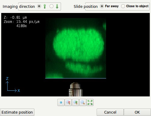
- The coverslip position editor showing an XZ Maximum Intensity Projection (MIP) of the data along the Y-direction. The coverslip position can be edited by dragging the blue line. The imaging direction, currently upwards, is indicated by the position of the objective relative to the data as shown. The Z-position shown top-left in the image indicates the distance in micron of the coverslip to the first data plane.
The coverslip position editor can be launched from:
- the Essential wizard during the parameter check stage,
- the Huygens Pro parameter wizard ('Set coverslip' button in 'Sampling density' stage),
- the Huygens Pro parameter editor (button with wrench icon).
Imaging Direction
Inverted microscope
In an inverted microscope the objective lens points upwards. The editor shows the coverslip position and imaging direction relative to the data as read from the microscopic file. In an inverted microscope, with the objective physically below the specimen it is likely that the first XY plane in the data, corresponding with the lowest location in the XZ MIP on the screen, corresponds with the XY plane scanned closest to the objective. This situation is shown in the figure above. However, since scan directions and data planes might have been reordered, this match is not guaranteed. Fortunately, it is often easy to spot the flat side of the object where it adheres to the glass, so the orientation can be verified.
Upright microscope
An upright microscope has the objectoive above the sample table. So, the objective lens is pointing downwards. In such an upright microscope, with a Z scan starting further away from and coming closer to the coverslip, the first plane is also likely to be physically the lowest plane. In that case, the imaging direction should be set to downwards and the coverslip position in the top part of the MIP projection. However, if the scan started close to the coverslip while storing these first planes first in the data set, the MIP projection will show the data upside down. Consequently, the coverslip position will be in the lower part of the MIP, and the imaging direction is upward.
Slide position
When the specimen is mounted on the coverslip, the distance from the object to the slide is probably in the range 50-100 micron, outside of the image. In this case, or in the case there is no slide, select 'Far away' in the top-right selector.
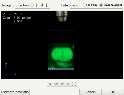
- The Coverslip editor with the slide position set to 'Close to object'. The slide is indicated by the striped box.
When the specimen is close to or mounted on the slide, select 'Close to object'. Drag the coverslip to its proper location. When this location is at some distance from the data it might be necessary to zoom out. The image can be dragged by holding down the right mouse button. In terms of imaging quality, when there is a refractive index mismatch between embedding medium and immersion medium, this is not an ideal situation since the light from and to the objective must travel hundreds of wavelengths through the embedding medium, possibly resulting in strong spherical aberration inducing bloating of the PSF.