
Visualizing your data after deconvolution
The importance of color, contrast and background settings
Whenever you deconvolve an image, you might notice that the contrast in your image has changed compared to the raw data. This is because out-of-focus light and blurred light has been re-assigned by the deconvolution algorithm to the location where the light most likely originated from. In addition, background signal has been removed from the raw data. Note that the Huygens MLE algorithms conserve the intensities, so your deconvolution results will still be quantifiable, and even moreso, the deconvolved results will be much easier to analyze compared to the raw data.
Since the background signal is removed, and light has been re-assigned by deconvolution, the contrast settings that might have worked well on your raw data, might not be the optimal choice for your deconvolved result. Therefore it may be useful to change for example the color scheme, brightness, or gamma scaling to adjust contrast. Here we show some practical and interactive examples and comparisons, and how the various color, contrast and background settings in the Huygens visualization tools can help you to optimally visualize your deconvolution results.
Try out different color schemes
Bring some colors and contrast to your research!
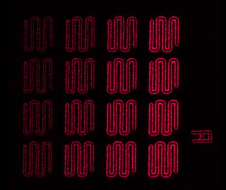

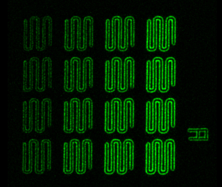
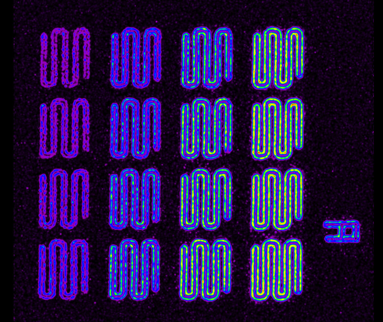
Using a different color setting can help to visualize dim structures. Red and blue typically give a low contrast on a black background, whereas bright-green or greyscale can help to visualize dim structures. The False color scheme can help even further to clearly visualize even the dimmest intensities. With False colors, the intensities will be displayed with different colors. With this interactive example you can explore the various color schemes and their difference in contrast: just click on the different buttons to see the difference of the choice of color can make!
In Huygens you can choose between Emission colors (which reflect the colors of your emission wavelengths for the various channels), global colors (which follow a global color scheme set in the preferences), False colors (good for visualizing dim signals), grayscale (good for high contrast) or custom colors (to set to any RGB color of your choice).
Using a different color setting can help to visualize dim structures. Red and blue typically give a low contrast on a black background, whereas bright-green or greyscale can help to visualize dim structures. The False color scheme can help even further to clearly visualize even the dimmest intensities. With False colors, the intensities will be displayed with different colors. With this interactive example you can explore the various color schemes and their difference in contrast: just click on the different buttons to see the difference of the choice of color can make! In Huygens you can choose between Emission colors (which reflect the colors of your emission wavelengths for the various channels), global colors (which follow a global color scheme set in the preferences), False colors (good for visualizing dim signals), grayscale (good for high contrast) or custom colors (to set to any RGB color of your choice).
Sample & image description: Aroglight (www.argolight.com) HM-slide, intensity gradient pattern. Image acquired on a Leica TCS SP8 confocal by Jeroen Kole, VUmc, Amsterdam, the Netherlands.
Try out different contrast settings
Boost the low signal in your images
contrast setting
contrast setting
Visualization settings can make a huge difference! In this example you can see the effect of gamma contrast scaling. When you visualize your data with improper contrast settings, the low signal data can be barely visible or perhaps not visible at all. Expecially when there is a large dynamic range in your image, this can make challenging to visualize the lower signal objects. Deconvolution increases the dynamic range in your image signficantly, so you might need to set the contrast settings differently compared to the raw data. By enhancing the brightness/contrast and color settings, it is possible to boost the lower signal relatively compared to the high signal objects in your image. The brightness and contrast settings in the various Huygens visualization tools do not alter your data: they are merely a tool to improve the visualization of your images.
Background subtraction
Keeping the low signal intact
can result in signal loss
All signal is preserved
The powerful automatic background subtraction integrated in the Huygens deconvolution software, is extremely robust and works very well on both high-signal and low signal data. In the Huygens Deconvolution Wizard and Batch processor you also have the flexibility of setting a fixed (manual) background. However, if you use a manual background, always make sure that you are not setting this manual background too high, so be careful especially with very low signal data. When you see that dim objects are gone after deconvolution, even after optimizing the visualization then this is often caused by a high manual background setting. Use either the auto-background estimation, or lower your manual background setting. This example image shows the difference between the auto-background estimation and a manual background setting which was set too high. This is low signal data (single photon counted), so extra care must be taken when using a manual background setting. Auto background estimation is often a better (and safer) choice.
Inspect the entire z-stack
Deconvolution re-assigns out-of-focus light!
Deconvolution is an image restoration process. The MLE algorithms in Huygens use some a-priory knowledge (such as the PSF and information on the noise in your image), to restore the objects in your 3D dataset as best as possible. Every microscope (even confocal systems) will still include out-of-focus light in the various z-slices in the raw dataset. In other words: in the raw data you might see some some out-of-focus light in each z-plane, that is actually originating from a plane above or below the current plane that you are viewing. This out-of-focus light will also have an effect on the contrast in your image. After deconvolution, the signal has been re-assigned to the correct planes, and in the deconvolved result it might appear as if some signal has dissapeared from the individual planes. However, when you look at the entire z-projection of the 3D dataset, you will notice that all structures are still present across the 3D volume; the light has merely been re-assigned to the correct location in the volume, and gives a more accurate represation of the actual 3D objects.
single z-plane
includes out-of-focus light
single z-plane
out-of-focus light
is re-assigned
MIP
MIP
Left: Single z-slice from a 3D z-stack. Notice that when visualizing a single slice, it may appear that some signal has been lost in the deconvolution, but in fact, this out-of-focus signal is still present but re-assigned to adjecent z-planes. Deconvolution improves the axial resolution, so any out-of-focus light will be re-assigned to the z-position as where it originated from. Rigth: Z-MIP projection of the same 3D z-stack. Notice that when you visualize the entire z-projection (either in the form of MIP or SUM mode), you can see that all the objects in the image are still present. The Huygens deconvolution has significantly improved the contrast and resolution in the image, including resolution in Z. Always inspect the entire z-stack of your (deconolved) image. A MIP or SUM project can help with this.