
Yokogawa disk
The Yokogawa Electric Corporation devised a unique Nipkow disk system with another coaxial spinning disk containing an array of microlenses, which efficiently guides the laser beams into pinholes.
Akihiko Nakano; Spinning-disk Confocal Microscopy: A Cutting Edge Tool for Imaging of Membrane Traffic. Cell Struct. Funct., Vol. 27, 349-355 (2002).
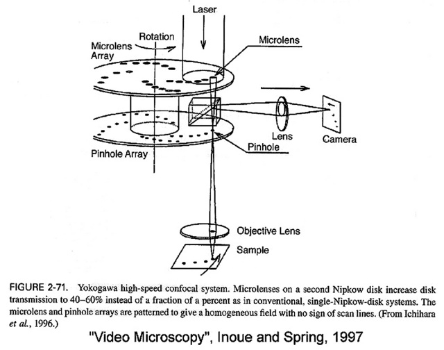
This page explains the principles of the microlens-enhanced Nipkow disk scanning technology.
Yokogawa disk in Huygens
A typical disk has a physical pinhole spacing of about 253 microns and pinhole radius of 25 microns (50 µm in diameter). While Yokogawa has different CSU heads on the market (CSU-10, CSU-22, CSU-X1, CSU-W1) the pinhole size and the design are basically the same.
If you want to process images made with a Nipkow Disk Microscope containing a Yokogawa disk in the Huygens Software, you must use the Back Projected values, not the physical ones directly. The necessary values are the physical ones divided by the total magnification. Note that any additional magnification that is positioned in front of the camera lens and not between the disk and the specimen plance doesn't need to be included in this "total magnification" since it does not influence how the pinhole size and distances of the spinning disk are projected on the specimen plane. In the following tables you can find the values for some typical Yokogawa magnifications. Below these tables you will find the calculation aid for all other Spinning Disc systems:
Yokogawa disk (CSU-10, CSU-22, CSU-X1)
| Magnification | Back Projected Pinhole Radius | Back Projected Pinhole Distance |
|---|---|---|
| 100× | 250 nm | 2.53 µm |
| 60× | 416.7 nm | 4.22 µm |
| 40× | 625 nm | 6.33 µm |
| 20× | 1250 nm | 12.7 µm |
| 10× | 2500 nm | 25.3 µm |
Yokogawa disk (CSU-W1 - 50 micron diameter pinhole (25 micron radius)
| Magnification | Back Projected Pinhole Radius | Back Projected Pinhole Distance |
|---|---|---|
| 100× | 250 nm | 5 µm |
| 60× | 416.7 nm | 8.33 µm |
| 40× | 625 nm | 15 µm |
| 20× | 1250 nm | 30 µm |
| 10× | 2500 nm | 50 µm |
Yokogawa disk (CSU-W1 - 25 micron diameter pinhole (12.5 micron radius)
| Magnification | Back Projected Pinhole Radius | Back Projected Pinhole Distance |
|---|---|---|
| 20× | 625 nm | (needs confirmation) |
With any spinning disk, the precise values can be measured precisely for any type magnification by simply stopping the disk and imaging the illumination pattern without any sample, as in the following image. This can be easily done by opening the image of the disk in the Twin Slicer and using the mouse cursor to measure the pinhole distance and sizes. This approach will give you the exact parameters as shown in the tables. Note that for the microscopy parameters, we use radius and not the diameter.
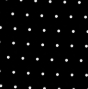 Image of a stopped CSU 22 confocal spinning disk recorded with a 60× - 1.42 NA objective, acquired by Dr. Paula Sampaio, Advanced Light Microscopy Facility, University of Porto. Pixel size 138.5 nm.
See Pinhole Distance and Difficulties Calculating The Pinhole for more details.