
Difficulties calculating the backprojected pinhole radius
The Back Projected Pinhole Radius is simply the real radius divided by the total magnification of the microscope. This (and not the real radius) is the figure that the Huygens Software needs when Doing Deconvolution on images acquired using Fluorescence Microscopes that use pinholes.
The problem now is that these two magnitudes are not always easy to find.
1) Because what matters is the total magnification, you must consider not only the objective magnification (which is usually easy to read from the lens barrel), but also any other amplification factor due to other lenses laying in between the pinhole and the sample. In many cases there is an extra fixed amplification (what we call the system magnification, m_sys) apart from the objective's, that varies a lot from one microscope model to another and that is usually unknown to the user. In many cases, not reported at all by the manufacturers in the technical specifications.
2) A question that is often asked is whether the internal magnification should be added to the total maginfication and whether that influences the BPP size. The answer is that the magnification between the spinning-disc and the camera does not play a role in de table values for the BPP sizes since it is not in the path between the disk and the specimen plane where the pinhole is back-projected. It does play a role however in the imaging of the stalled disk, so it influences the pixel-sizes in the resulting dataset. It is probably needless to say that the pixel sizes should be correctly defined to make any measurements from the imaged disk accurate. See also the Huygens Microscopy Parameter Editor.
3) Other difficulty is knowing the real pinhole size. The user can't simply measure it with a rule (the pinhole is in any case inaccessible in most configurations) and they must trust some value reported from the microscope interface. This value, depending on the microscope model, can be in many different units: the microscope can report the current pinhole diameter in meters, or the radius in microns, or the diagonal of a square in Airy Disk units, or a square side in standard-European-hair-width or the radius in number of full WaveLengths, even lightyears. Whatever you can imagine.
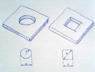
4) As already pointed, there's a third factor to be considered: the geometry of the pinhole. The value expected by Huygens to calculate the PSF refers to a circular-equivalent pinhole. If the actual pinhole shape in the microscope is square, a geometry conversion factor must be used that transforms the reported length d into a radius r of a circle that has equivalent total section. For a square pinhole where d is the side length, the equal geometrical areas give
$$d^2 = \pi r^2$$
and thus
$$r = \frac{d}{\sqrt{\pi}}$$
For a square pinhole the shape factor is therefore c = 1/sqrt(π) ~ 0.564 when the side length is reported, or c = 1/sqrt(2π) ~ 0.399 when the diagonal is reported. For circular pinholes c = 0.5 converts the reported parameter from diameter to radius.
The forms in the Backprojected Pinhole Calculator will assist you in getting the (circular-equivalent) backprojected pinhole radius expressed in nanometers for different microscope brands and models, that you can directly use when Doing Deconvolution with the Huygens Software.
Go to the Backprojected Pinhole Calculator.