
Image Formation
How waves behave
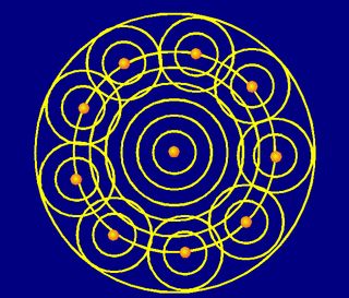
To understand the image formation in a microscope, we will make use of the Huygens Principle. It is just a simplified model to describe the behavior of waves in space. It applies to situations like this: imagine a single mathematical point source emiting radiation in all directions. This radiation can be any type of waves, like sound or visible light. Without any obstacle, this radiation is "equal" in all directions, it has a spherical wave front traveling away from the source. To describe how this wave propagates in space, how its shape would be a moment later based on its shape at present time, we can imagine the original wave at any moment as if it were "exciting" the points of the space that it reached. These points behave themselves as new sources of radiation. The Huygens-Fresnel principle says that the shape of the wave front a moment later comes from the sum of all the waves arising from these secondary sources. As we actually have infinite secondary point sources in a spherical disposition, the addition of all their wave fronts makes again a spherical wave front that keeps propagating, again and again, from one sphere to the next one around it.
If we put now an obstacle in the way of the spherical wave front we avoid the excitation of some of the secondary sources. Therefore, the resulting addition of secondary fronts will no longer produce a sphere.
If the obstacle is an infinite wall, no radiation will cross to the other side. If we make a small hole in this wall, only the interior of the hole will get excited and emit to the other side. An observer on the other side of the wall will detect radiation as being emitted by the hole itself, in a particular wave front that depends on the shape of the hole.
This simple idea helps to understand a lot of phenomena, such as diffraction. For example, if two rooms are connected by an open doorway and a sound is produced in a remote corner of one of them, a person in the other room will hear the sound as if it originated at the doorway. As far as the second room is concerned, the vibrating air in the doorway is the source of the sound. The same is true of light passing the edge of an obstacle, but this is not as easily observed because of the shorter wavelength of visible light (wikipedia).
Role of the objective
We can see a focusing (convergent) lens as an optical device that, by introducing the appropriate delays in the light paths (more delay in the center, and less in the borders) "inverts" the shape of a spherical wave front coming from a punctual source in the object. At the other side of the lens (the image side) points of the space are excited and become secondary sources in such a way that they produce an inverted (mirrored) spherical wave front.
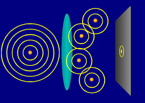
At the central point of that new sphere (the focus, that is at equal distance from all the secondary sources), all the wave fronts from the secondary sources arrive in phase, resulting in a constructive interference. If we put there a screen or a detector, we will see a hight intensity point at the focus. At any other point away from the center some waves will arrive "almost" in phase, but many others will have "almost" opposite phase, so the interference is not totally constructive, and the resulting intensity decreases. The further we go away from the center, the more destructive is the average resulting interference. These intensity changes depend on the WaveLength: the shorter the wavelength, the more rapidly the intensity decays.
But the lens did not trap the whole original wave front to transform it all. It was able to "invert" only the part of the wave front that it was able to collect, due to its limited size. (From the point of view of the image side, the rest of the original sphere is lost information). Thus, the converging spherical wave front is not a full sphere, but only a small portion of it. We have not enough secondary sources to annihilate, in destructive interference, the intensity away from the center. As we move away from the focus the intensity decreases smoothly during a certain distance until it reaches a minimum, but then it increases again!!! (Some constructive interference is obtained periodically).
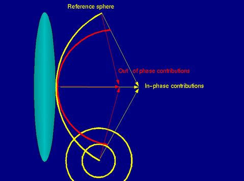
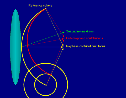 The reference sphere (yellow) is the secondary spherical cap generated by the lens at the image side, centered at the focus. The red spherical cap is similar to the previous one, but centered in a point of interest, away from the focus, with the minimum radius that makes it touch the reference at one point. If the distance at the other extreme between both spherical caps is exactly an odd number of WaveLengths, the interference in the point of interest is basically destructive and we have a local minimum. If it is an even number of wavelength, the interference is constructive and we have a local maximum.
The resulting pattern of light on the screen is a typical central Airy Disk with rings of light around it:

The amount of light that a lens can collect is measured by its Numerical Aperture. The size of an Airy Disk depends on the WaveLength of the radiation and the Numerical Aperture of the objective lens, not on its magnification. Using dimensionless coordinates, the radius of an Airy Disk is 3.83 Optical Units.
The Airy disk and the rings around it is the pattern obtained in a 2D slice in the image plane, but the interference behavior described above is obtained similarly also along the optical axis:
If we image the point source in a volumic 3D Image, we obtain some kind of 3D Airy disk: the Point Spread Function (PSF).
Resolution
We have seen how a single point source produces a disk in the image plane (a PSF in the image volume), not a point anymore. If two original source points are too close to each other they will produce overlapping disks, that eventually become indistinguishable. This limit of resolution is given by the Rayleigh Criterion. Thus, we see how the radiation WaveLength and the Numerical Aperture of the objective limits our resolution!!!
With small apertures the distance from the focus in which the first zero lies is larger than with large apertures. Therefore, high aperture system have higher resolution. In high aperture systems the vector character of light makes it necessary to replace the superposition of 'amplitudes' (the Paraxial Simplification) by that of vectors, when calculating the resulting intensity in any point of the image space.
But despite resolution is physically limited, we should not limit it even more by not recording all the available information. Acquiring the image by digital means must allow us to record full Airy Disks (full PSF's in a 3D image), and therefore an appropriate sampling is required. If our Sampling Distances are larger than the Airy disks (UnderSampling), we are wasting optical resources not collecting all the information that the microscope provides. If the sampling is too tight (OverSampling), we may be wasting storage resources collecting redundant information. The correct Sampling Density is determined by the Nyquist Criterion.
Building the image
We have seen how a single point source is registered by a 3D Microscope as a complex 3D intensity distribution, namely the Point Spread Function. In Linear System like Fluorescence Microscopes, we can consider that the whole image as acquired by the microscope is build up by all the contributions from the different original light sources, each generating a PSF.
Therefore the image arises from a sum of PSFs, each shifted to the location and scaled according to the intensity of the corresponding point. This is mathematically represented by a Convolution equation.
See Point Spread Function and Convolution.
External links
- Diffraction: http://www.gonda.ucla.edu/bri_core/diffract.htm
- Numerical aperture: http://micro.magnet.fsu.edu/primer/anatomy/numaperture.html
- Resolution: http://www.olympusconfocal.com/theory/resolutionintro.html
- Huygens' principle: http://www.mathpages.com/home/kmath242/kmath242.htm