Crosstalk (or bleed-through) is the erroneous detection of a signal in another channel when performing fluorescence microscopy with multiple dyes. Signal from coming form one dye is then detected and shown across multiple channels. Crosstalk can occur when the excitation and emission spectra overlap when using multiple fluorescent dyes (fluorophores). Crosstalk severely affects all image analysis and must be avoided to ensure correct and reliable data analysis. The Huygens crosstalk corrector can detect and correct crosstalk within images after acquisition.
Hypothetical emission spectra of a cyan (channel 1) and yellow (channel 2) fluorescent dye. Grey regions mark the wavelengths that are picked up as crosstalk by the different filter sets. The images to the right are a graphical representation of how crosstalk would appear in the image. Due to crosstalk, both channels show faint structures that originate from the other dye.

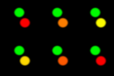
The animation on the left shows red signal entering the green detector in a two channel image. The sample is composed of two non-overlapping objects dyed red and green. The higher the crosstalk factor, the more yellow the red object looks, because its signal is recorded not only in the red channel but also in the green one. The crosstalk from the green to the red channel is considered to be zero in this simplified case.
Causes of crosstalk
Crosstalk depends on a few factors, which are the excitation and emission spectra of the used fluorophores and the wavelength filters used during acquisition. A distinction can be made between two main sources of crosstalk; 1) excitation crosstalk, when multiple fluorophores are excited by a single excitation wavelength and 2) emission crosstalk, when emission wavelengths of multiple fluorophores are detected in the same channel.Crosstalk, bleed-through or spectral crossover are all commonly used terms to describe artifacts occurring due to interference between dyes in fluorescence microscopy. For consistency, any form of this phenomenon (caused by either excitation or emission) is here referred to as crosstalk.
Each fluorophore has a specific excitation and emission spectra. The excitation spectrum describes the wavelengths that bring the fluorescent molecule into the ‘excited’ state, when the molecules return to the ‘ground’ state they emit a photon, the wavelengths of the emitted photons is described by the emission spectrum. Learn more about fluorescence microscopy here.
Hypothetical excitation spectra of two dyes excited in the blue (dye 1) and cyan (dye 2) light spectra. These dyes emit in the green and orange light spectra respectively. Red vertical lines represent the excitation laser used for each dye, the black circle marks the excitation crosstalk of dye 2.
Excitation crosstalk
Crosstalk due to excitation crossover happens when the laser used for exciting one of the fluorophores also (weakly) excites the other fluorophore. As excitation spectra are usually skewed towards the lower wavelengths (blue), this type of crosstalk usually causes “redder” fluorophores to become excited and emit light when exciting the “bluer” fluorophore. The figure shows two excitation spectra of green (dye 1) and orange (dye 2) emitting fluorophores. Excitation of dye 2 does not cause any issues, as the laser used for excitation (red vertical line) does not overlap with the excitation spectra of dye 1. However, the excitation laser used to excite dye 1 does overlap with the exciation spectra of dye 2, causing dye 2 to emit fluorescence when exciting dye 1. Excitation crosstalk does not have to be a problem, if the wavelength filters can adequately distinguish the emissions form both dyes.Emission crosstalk
If the emission spectra are of two fluorophores used in the sample are highly similar or overlapping, this makes it harder to distinguish between signal from either fluorophore. Wavelength filters present in fluorescent microscopes allow for distinction between two different fluorophores, as long as their emission spectra are sufficiently separated. However, if the emission spectra are very close or the used filters are set too broad, this results in detection of light from other fluorophores as well. Therefore, when planning experiments always select fluorophores with distinct emission spectra, and use the appropriate filters to avoid crosstalk. Most microscopes are equipped with mulitple different wavelength filters, allowing users to select different wavelength ranges based on the fluorophores in the sample.Emission crosstalk usually occurs more severe in the “redder” dye (i.e. wavelenghts emitted by a green fluorophore being detected in the red fluorophores channel). Therefore, to limit crosstalk, it is advised to always image the “redder” dye first. In the example of the green and orange emitting fluorophores, if the green dye (dye 1) is imaged first, this can result in some lingering light coming from the green fluorophore. When switching to the “orange” filter set to image dye 2, the detector can still record this lingering light as it partially overlaps with the emission spectrum of dye 2. When dye 2 is imaged first, there is generally less overlap between the emission spectra, alleviating the problem of lingering light and crosstalk.
Hypothetical emission spectra of two dyes, emitting in the green (dye 1) and orange (dye 2) light spectra. The green and orange shaded sections represent the wavelength filter boundaries for detecting each dye. Grey sections highlight overlap between the two emission spectra that falls within the filter ranges, this causes crosstalk.
Avoiding crosstalk
To avoid crosstalk, most microscopes excite each dye alternatively, making sure that all the detected signal comes from a single dye. However, some experiments (e.g. Fluorescence Resonance Energy Transfer - FRET) require simultaneous acquisition of signal from all the present dyes, with the possible risk of crosstalk.Moreover, as shown above, even with separate dye excitation crosstalk can still occur. Avoiding crosstalk can be done by choosing sets of fluorophores that have distinct excitation and emission spectra. In practice this might not always be possible as most spectra have long tails making some overlapping unavoidable.
In addition, always make sure the wavelength filters are not overlapping and detect as little of unwanted emission as possible. If two emission spectra are close, it might be beneficial to set the wavelength filters more narrow, to avoid light from the other fluorophore as much as possible. However, setting the filters comes with a trade-off, as this also limits the amount of signal you can obtain from the sample. If there is bleed-through due to overlapping emission spectra, it might be beneficial to change the imaging order and image the “redder” dyes first.
Detecting crosstalk
Crosstalk can be identified in a 2D histogram that plots the two channels intensities against each other. Crosstalk can be seen as ‘dark triangles’ on the sides of the histogram. These arise when all signal from one channel is also contributing to some signal in the other channel.
Mitochondrial (TMRM) red signal is also detected as signal in the green Lipid Droplet (BODIPY) channel due to crosstalk. This crosstalk will have a serious impact on the analysis of lipid droplet structure. Both channels are shown in the upper part; only the green channel is shown in the lower part. The spinning disk image was corrected with Huygens Crosstalk Corrector (right). Courtesy of Kevin Knoops (Microscopy CORE Lab), Sabine Daemen and Matthijs Hesselink, Maastricht University, The Netherlands.
Crosstalk correction with Huygens
After image acquisition, crosstalk or bleed-through is easily detectable by the Huygens software.Crosstalk in multi channel images dramatically affects nearly all types of data analysis, for example colocalization analysis. To ensure proper image analysis it should therefore be corrected through image restoration. To improve microscopy image quality and thereby allow for reliable image analysis, Huygens offers a Crosstalk Corrector tool to correct for this imaging artifact.
The main window of the Huygens Crosstalk Corrector before (left) and after (right) estimating the crosstalk.
References
1. https://www.olympus-lifescience.com/en/microscope-resource/primer/techniques/confocal/bleedthrough/2. https://www.ncbi.nlm.nih.gov/pmc/articles/PMC5703511/
